With ____, You Can Send Electrical Power Over the Ethernet Connection.
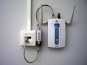
In this configuration, an Ethernet connectedness includes Ability over Ethernet (PoE) (gray cable looping beneath), and a PoE splitter provides a split up data cable (grayness, looping in a higher place) and power cable (black, too looping higher up) for a wireless access point (WAP). The splitter is the silver and black box in the heart betwixt the wiring junction box (left) and the access betoken (right). The PoE connectedness eliminates the demand for a nearby power outlet. In some other common configuration, the access betoken or other connected device includes internal PoE splitting and the external splitter is not necessary.
Power over Ethernet, or PoE, describes any of several standards or advertisement hoc systems that pass electric power along with data on twisted-pair Ethernet cabling. This allows a unmarried cable to provide both data connection and electric power to devices such as wireless admission points (WAPs), Internet Protocol (IP) cameras, and voice over Internet Protocol (VoIP) phones.
There are several common techniques for transmitting power over Ethernet cabling. Three of them have been standardized by Institute of Electrical and Electronics Engineers (IEEE) standard IEEE 802.3 since 2003. These standards are known as alternative A, culling B, and 4PPoE. For 10BASE-T and 100BASE-TX, only two of the four betoken pairs in typical True cat 5 cable are used. Alternative B separates the data and the power conductors, making troubleshooting easier. Information technology also makes full use of all four twisted pairs in a typical Cat 5 cablevision. The positive voltage runs along pins 4 and 5, and the negative along pins 7 and 8.
Alternative A transports power on the same wires as data for x and 100 Mbit/south Ethernet variants. This is similar to the phantom power technique commonly used for powering condenser microphones. Ability is transmitted on the information conductors by applying a common voltage to each pair. Because twisted-pair Ethernet uses differential signaling, this does non interfere with data transmission. The mutual-mode voltage is easily extracted using the center tap of the standard Ethernet pulse transformer. For Gigabit Ethernet and faster, both alternatives A and B transport ability on wire pairs besides used for information since all four pairs are used for information transmission at these speeds.
4PPoE provides power using all four pairs of a twisted-pair cable. This enables higher power for applications like Pan–Tilt–Zoom (PTZ) cameras, high-performance WAPs, or even charging laptop batteries.
In addition to standardizing existing practice for spare-pair (Alternative B), common-way information pair power (Culling A) and 4-pair transmission (4PPoE), the IEEE PoE standards provide for signaling between the power sourcing equipment (PSE) and powered device (PD). This signaling allows the presence of a conformant device to be detected by the power source, and allows the device and source to negotiate the corporeality of power required or bachelor.
Standards development [edit]
Ii- and four-pair Ethernet [edit]
The original IEEE 802.3af-2003 [1] PoE standard provides up to xv.4 W of DC ability (minimum 44 V DC and 350 mA)[2] [3] on each port.[4] Only 12.95 W is bodacious to be available at the powered device as some power dissipates in the cablevision.[v] The updated IEEE 802.3at-2009 [6] PoE standard also known equally PoE+ or PoE plus, provides up to 25.v W of power for Type 2 devices.[7] The 2009 standard prohibits a powered device from using all four pairs for power.[8] Both of these standards have since been incorporated into the IEEE 802.iii-2012 publication.[9]
The IEEE 802.3bt-2018 standard further expands the power capabilities of 802.3at. It is also known every bit PoE++ or 4PPoE. The standard introduces two additional ability types: upwards to 51 W delivered power (Blazon iii) and upward to 71.3 Westward delivered ability (Blazon four). Each pair of twisted pairs needs to handle a electric current of upward to 600 mA (Blazon 3) or 960 mA (Type four).[10] Additionally, support for ii.5GBASE-T, 5GBASE-T and 10GBASE-T is included.[eleven] This evolution opens the door to new applications and expands the use of applications such equally high-performance wireless access points and surveillance cameras.
Single-pair Ethernet [edit]
The IEEE 802.3bu-2016 [12] subpoena introduced single-pair Power over Data Lines ( PoDL ) for the single-pair Ethernet standards 100BASE-T1 and 1000BASE-T1 intended for automotive and industrial applications.[13] On the two-pair or four-pair standards, the same power voltage is applied to each usher of the pair, so that within each pair there is no differential voltage other than that representing the transmitted data. With unmarried-pair Ethernet, ability is transmitted in parallel to the data. PoDL initially defined ten power classes, ranging from 0.5 to fifty W (at PD).
Later on, PoDL was added to the single-pair variants 10BASE-T1,[14] 2.5GBASE-T1, 5GBASE-T1, and 10GBASE-T1[xv] and equally of 2021[update] includes a full of 15 power classes with additional intermediate voltage and power levels.[fourteen]
Uses [edit]
-

-

A CableFree FOR3 microwave link installed in the UAE: a full outdoor radio featuring proprietary high power over Ethernet
Examples of devices powered by PoE include:[16]
- VoIP phones
- IP cameras including PTZs
- WAPs
- IP Tv set (IPTV) decoders
- Network routers
- A mini network switch installed in distant rooms, to support a small cluster of Ethernet ports from one uplink cable. PoE power is fed into the PD (or PoE in) port. These switches may in turn ability remote PoE devices using PoE laissez passer through.
- Intercom and public address systems and hallway speaker amplifiers
- Wall clocks in rooms and hallways, with time set using Network Time Protocol (NTP)
- Outdoor roof mounted radios with integrated antennas, 4G/LTE, 802.11 or 802.xvi based wireless CPEs (customer premises equipment) used by wireless ISPs
- Outdoor betoken to bespeak microwave and millimeter moving ridge radios and some Free Infinite Optics (FSO) units usually featuring proprietary PoE
- Industrial control arrangement components including sensors, controllers, meters etc.
- Access control components including help-points, intercoms, entry cards, keyless entry, etc.
- Intelligent lighting controllers and Light-Emitting Diode (LED) Lighting fixtures[17]
- Phase and Theatrical devices, such every bit networked audio breakout and routing boxes
- Remote Point Of Sale (POS) kiosks
- Inline Ethernet extenders[eighteen]
- PoE Splitters that output the ability, often at a different voltage (eastward.k. 5V), to ability a remote device or charge a mobile phone
Terminology [edit]
Power sourcing equipment [edit]
Ability sourcing equipment (PSE) are devices that provide (source) power on the Ethernet cablevision. This device may be a network switch, commonly chosen an endspan (IEEE 802.3af refers to information technology as endpoint), or an intermediary device between a non-PoE-capable switch and a PoE device, an external PoE injector, called a midspan device.[19]
Powered device [edit]
A powered device (PD) is any device powered past PoE, thus consuming free energy. Examples include wireless admission points, VoIP phones, and IP cameras.
Many powered devices take an auxiliary ability connector for an optional external power supply. Depending on the design, some, none, or all of the device'south power can be supplied from the auxiliary port,[20] [21] with the auxiliary port also sometimes interim every bit backup power in case PoE-supplied power fails.
Power management features and integration [edit]

Advocates of PoE expect PoE to go a global long term DC ability cabling standard and supervene upon a multiplicity of individual Air conditioning adapters, which cannot be easily centrally managed.[22] Critics of this approach argue that PoE is inherently less efficient than Air conditioning power due to the lower voltage, and this is made worse by the sparse conductors of Ethernet. Advocates of PoE, like the Ethernet Alliance, bespeak out that quoted losses are for worst case scenarios in terms of cable quality, length and power consumption past powered devices.[23] In whatsoever case, where the central PoE supply replaces several defended AC circuits, transformers and inverters, the power loss in cabling tin be justifiable.
Integrating EEE and PoE [edit]
The integration of PoE with the IEEE 802.3az Energy-Efficient Ethernet (EEE) standard potentially produces boosted energy savings. Pre-standard integrations of EEE and PoE (such as Marvell's EEPoE outlined in a May 2011 white paper) merits to achieve a savings upward of 3 W per link. This saving is specially significant as higher power devices come online.[24]
Standard implementation [edit]
Standards-based Power over Ethernet is implemented following the specifications in IEEE 802.3af-2003 (which was later incorporated every bit clause 33 into IEEE 802.3-2005) or the 2009 update, IEEE 802.3at. The standards crave category 5 cable or better for high ability levels but allow using category 3 cable if less power is required.[25]
Power is supplied every bit a common-mode betoken over ii or more of the differential pairs of wires constitute in the Ethernet cables and comes from a ability supply inside a PoE-enabled networking device such as an Ethernet switch or can be injected into a cablevision run with a midspan power supply, an additional PoE ability source that tin be used in combination with a non-PoE switch.
A phantom power technique is used to permit the powered pairs to also comport data. This permits its use not only with 10BASE-T and 100BASE-TX, which utilize only 2 of the iv pairs in the cablevision, merely besides with 1000BASE-T (gigabit Ethernet), 2.5GBASE-T, 5GBASE-T, and 10GBASE-T which use all four pairs for information transmission. This is possible because all versions of Ethernet over twisted pair cablevision specify differential data manual over each pair with transformer coupling; the DC supply and load connections can be made to the transformer centre-taps at each end. Each pair thus operates in common mode as one side of the DC supply, so 2 pairs are required to complete the excursion. The polarity of the DC supply may exist inverted by crossover cables; the powered device must operate with either pair: spare pairs 4–5 and 7–viii or information pairs i–ii and 3–6. Polarity is divers by the standards on spare pairs, and ambiguously implemented for data pairs, with the use of a diode bridge.
| Property | 802.3af (802.3at Type 1) "PoE" | 802.3at Type two "PoE+" | 802.3bt Type three "4PPoE"[26]/"PoE++" | 802.3bt Type four "4PPoE"/"PoE++" |
|---|---|---|---|---|
| Power available at PD[annotation 1] | 12.95 Westward | 25.50 W | 51 W | 71 W |
| Maximum power delivered by PSE | 15.40 W | thirty.0 Westward | 60 West | 100 W [note two] |
| Voltage range (at PSE) | 44.0–57.0 V [27] | 50.0–57.0 V [27] | 50.0–57.0 Five | 52.0–57.0 Five |
| Voltage range (at PD) | 37.0–57.0 V [28] | 42.5–57.0 V [28] | 42.v–57.0 V [29] | 41.1–57.0 V |
| Maximum current Imax | 350 mA [thirty] | 600 mA [thirty] | 600 mA per pair[29] | 960 mA per pair[29] |
| Maximum cable resistance per pairset | 20 Ω [31] (Category 3) | 12.5 Ω [31] (Category 5) | 12.v Ω [29] | 12.5 Ω [29] |
| Power management | 3 power grade levels (i-3) negotiated by signature | Iv ability class levels (1-iv) negotiated by signature or 0.1 W steps negotiated by LLDP | Six power grade levels (1-6) negotiated by signature or 0.i W steps negotiated past LLDP[32] | 8 power class levels (i-8) negotiated past signature or 0.1 W steps negotiated by LLDP |
| Derating of maximum cable ambient operating temperature | None | v °C (9 °F) with one way (two pairs) active | 10 °C (xx °F) with more than one-half of bundled cables pairs at Imax [33] | 10 °C (20 °F) with temperature planning required |
| Supported cabling | Category 3 and Category 5[25] | Category 5[25] [note 3] | Category 5 | Category five |
| Supported modes | Way A (endspan), Mode B (midspan) | Mode A, Style B | Way A, Manner B, 4-pair Mode | 4-pair Fashion Mandatory |
Notes:
- ^ Almost switched-style power supplies within the powered device will lose another 10 to 25% of the bachelor power to heat.
- ^ ISO/IEC 60950 Safety Extra Low Voltage (SELV) standard limits ability to 100 W per port (like to US NEC class 2 circuit).
- ^ More stringent cable specification allows supposition of more electric current carrying capacity and lower resistance (20.0 Ω for Category 3 versus 12.5 Ω for Category 5).
Powering devices [edit]
Three modes, A, B, and 4-pair are bachelor. Style A delivers power on the information pairs of 100BASE-TX or 10BASE-T. Style B delivers ability on the spare pairs. four-pair delivers power on all four pairs. PoE can also exist used on 1000BASE-T, 2.5GBASE-T, 5GBASE-T and 10GBASE-T Ethernet, in which case in that location are no spare pairs and all power is delivered using the phantom technique.
Manner A has two alternate configurations (MDI and MDI-X), using the same pairs just with different polarities. In mode A, pins 1 and 2 (pair #ii in T568B wiring) form one side of the 48 Five DC, and pins 3 and 6 (pair #three in T568B) form the other side. These are the aforementioned two pairs used for data transmission in 10BASE-T and 100BASE-TX, allowing the provision of both power and data over just two pairs in such networks. The free polarity allows PoE to adjust for crossover cables, patch cables and Auto MDI-X.
In fashion B, pins 4–5 (pair #i in both T568A and T568B) course one side of the DC supply and pins seven–8 (pair #4 in both T568A and T568B) provide the return; these are the "spare" pairs in 10BASE-T and 100BASE-TX. Mode B, therefore, requires a iv-pair cable.
The PSE, not the PD, decides whether power mode A or B shall be used. PDs that implement just mode A or fashion B are disallowed by the standard.[34] The PSE can implement style A or B or both. A PD indicates that it is standards-compliant by placing a 25 kΩ resistor between the powered pairs. If the PSE detects a resistance that is also high or too low (including a short circuit), no power is applied. This protects devices that do not support PoE. An optional power class feature allows the PD to indicate its power requirements by irresolute the sense resistance at higher voltages.
To retain power, the PD must use at to the lowest degree 5–x mA for at least 60 ms at a time. If the PD goes more than 400 ms without coming together this requirement, the PSE volition consider the device disconnected and, for safe reasons, remove power.[35]
There are ii types of PSEs: endspans and midspans. Endspans (commonly called PoE switches) are Ethernet switches that include the power over Ethernet transmission circuitry. Midspans are power injectors that stand between a regular Ethernet switch and the powered device, injecting ability without affecting the data. Endspans are commonly used on new installations or when the switch has to be replaced for other reasons (such as moving from x/100 Mbit/s to 1 Gbit/south), which makes it convenient to add the PoE capability. Midspans are used when there is no desire to supplant and configure a new Ethernet switch, and just PoE needs to exist added to the network.
| Stage | Activity | Volts specified (V) | |
|---|---|---|---|
| 802.3af | 802.3at | ||
| Detection | PSE detects if the PD has the correct signature resistance of xix–26.5 kΩ | 2.seven–10.one | |
| Classification | PSE detects resistor indicating power range (run into below) | xiv.five–20.5 | |
| Mark ane | Signals PSE is 802.3at capable. PD presents a 0.25–iv mA load. | — | 7–x |
| Class ii | PSE outputs nomenclature voltage again to point 802.3at capability | — | xiv.5–20.5 |
| Mark two | Signals PSE is 802.3at capable. PD presents a 0.25–4 mA load. | — | 7–x |
| Startup | Startup voltage[36] [37] | > 42 | > 42 |
| Normal operation | Supply power to device[36] [37] | 37–57 | 42.5–57 |
IEEE 802.3at capable devices are also referred to as Type 2. An 802.3at PSE may besides use LLDP advice to betoken 802.3at adequacy.[38]
| Course | Usage | Classification current (mA) | Power range at PD (W) | Max power from PSE (Westward) | Course description |
|---|---|---|---|---|---|
| 0 | Default | 0–5 | 0.44–12.94 | 15.4 | Classification unimplemented |
| i | Optional | 8–thirteen | 0.44–three.84 | 4.00 | Very Low power |
| 2 | Optional | 16–21 | 3.84–half dozen.49 | seven.00 | Low power |
| 3 | Optional | 25–31 | six.49–12.95 | 15.four | Mid power |
| iv | Valid for Type 2 (802.3at) devices, non immune for 802.3af devices | 35–45 | 12.95–25.50 | 30 | High power |
| 5 | Valid for Type 3 (802.3bt) devices | 36–44 & 1–4 | 40 (4-pair) | 45 | |
| 6 | 36-44 & 9–12 | 51 (4-pair) | 60 | ||
| 7 | Valid for Type 4 (802.3bt) devices | 36–44 & 17–twenty | 62 (4-pair) | 75 | |
| 8 | 36–44 & 26–30 | 71.3 (4-pair) | 99 |
Grade iv can only exist used past IEEE 802.3at (Type two) devices, requiring valid Class 2 and Mark ii currents for the power upwards stages. An 802.3af device presenting a grade four current is considered non-compliant and, instead, volition be treated as a Class 0 device.[41] : xiii
Configuration via Ethernet layer 2 LLDP [edit]
Link Layer Discovery Protocol (LLDP) is a layer-ii Ethernet protocol for managing devices. LLDP allows an exchange of data between a PSE and a PD. This information is formatted in type–length–value (TLV) format. PoE standards define TLV structures used by PSEs and PDs to signal and negotiate available power.
| TLV Header | TLV data string | ||||||||
|---|---|---|---|---|---|---|---|---|---|
| Type (7 bits) | Length (nine $.25) | IEEE 802.3 OUI (3 octets) | IEEE 802.3 subtype (one octet) | MDI power support[43] (1 octet) | PSE power pair[43] (one octet) | Power class (i octet) | Type/source priority (ane octet) | PD requested power value (2 octets) | PSE allocated power value (ii octets) |
| 127 | 12 | 00-12-0F | ii | b0 port course: 1=PSE; 0=PD b1 PSE MDI power support b2 PSE MDI ability country b3 PSE pairs control ability b7-4 reserved | 1=signal pair ii=spare pair | 1=class 0 2=class 1 3=class 2 4=course 3 5=grade 4 | b7 power type: 1=Type 1; 0=Type 2 b6 power type: i=PD; 0=PSE b5-4: power source b3-2: reserved b0-1 power priority: 11=depression;x=high;01=critical;00=unknown | 0–25.v W in 0.1 W steps | 0–25.5 Due west in 0.1 W steps |
| TLV Header | TLV information string | |||||
|---|---|---|---|---|---|---|
| Type (7 bits) | Length (9 $.25) | IEEE 802.3 OUI (3 octets) | IEEE 802.three subtype (1 octet) | MDI power support[43] (1 octet) | PSE ability pair[43] (1 octet) | Ability class (1 octet) |
| 127 | 7 | 00-12-0F | two | b0 port class: ane=PSE; 0=PD b1 PSE MDI power support b2 PSE MDI power state b3 PSE pairs command ability b7-4 reserved | one=betoken pair 2=spare pair | 1=class 0 2=class 1 3=class 2 4=class iii 5=class 4 |
| TLV Header | MED Header | Extended ability via MDI | |||||
|---|---|---|---|---|---|---|---|
| Blazon (7 bits) | Length (nine $.25) | TIA OUI (3 octets) | Extended power via MDI subtype (1 octet) | Ability type (ii bits) | Power source (2 bits) | Ability priority (4 bits) | Power value (2 octets) |
| 127 | 7 | 00-12-BB | 4 | PSE or PD | Normal or Backup conservation | Critical, High, Low | 0–102.3 Due west in 0.1 W steps |
The setup phases are as follows:
- PSE (provider) tests PD (consumer) physically using 802.3af stage class 3.
- PSE powers up PD.
- PD sends to PSE: I'grand a PD, max power = Ten, max ability requested = 10.
- PSE sends to PD: I'thou a PSE, max power allowed = Ten.
- PD may now employ the amount of power every bit specified by the PSE.
The rules for this power negotiation are:
- PD shall never request more ability than physical 802.3af course
- PD shall never draw more than max power advertised by PSE
- PSE may deny any PD drawing more than power than max allowed by PSE
- PSE shall non reduce ability allocated to PD that is in use
- PSE may request reduced power, via conservation mode[45] : ten
Not-standard implementations [edit]
Cisco [edit]
Some Cisco WLAN access points and VoIP phones supported a proprietary grade of PoE[46] many years before there was an IEEE standard for delivering PoE. Cisco'due south original PoE implementation is not software upgradeable to the IEEE 802.3af standard. Cisco's original PoE equipment is capable of delivering up to 10 W per port. The amount of power to be delivered is negotiated between the endpoint and the Cisco switch based on a power value that was added to the Cisco proprietary Cisco Discovery Protocol (CDP). CDP is also responsible for dynamically communicating the Voice VLAN value from the Cisco switch to the Cisco VoIP Phone.
Under Cisco'southward pre-standard scheme, the PSE (switch) will send a fast link pulse (FLP) on the transmit pair. The PD (device) connects the transmit line to the receive line via a low-laissez passer filter. The PSE gets the FLP in return. The PSE will provide a common mode current between pairs 1 and 2, resulting in 48 V DC [47] and 6.iii W [48] default of allocated ability. The PD must then provide Ethernet link inside v seconds to the motorcar-negotiation mode switch port. A later CDP message with a TLV tells the PSE its last ability requirement. A discontinuation of link pulses shuts down power.[49]
In 2014, Cisco created another non-standard PoE implementation chosen Universal Power over Ethernet (UPOE). UPOE can use all 4 pairs, subsequently negotiation, to supply up to sixty W.[fifty]
Linear Technology [edit]
A proprietary loftier-power development called LTPoE++, using a unmarried CAT-5e Ethernet cable, is capable of supplying varying levels at 38.seven, 52.vii, seventy, and ninety Westward.[51]
Microsemi [edit]
PowerDsine, acquired by Microsemi in 2007, has been selling midspan power injectors since 1999 with its proprietary Power over LAN solution. Several companies such as Polycom, 3Com, Lucent and Nortel utilize PowerDsine's Power over LAN.[52]
Passive [edit]
In a passive PoE arrangement, the injector does not communicate with the powered device to negotiate its voltage or wattage requirements, but merely supplies power at all times. The mutual 100 Mbit/southward passive applications utilize the pinout of 802.3af mode B (see § Pinouts) – with DC positive on pins four and 5 and DC negative on 7 and eight and information on 1-2 and iii-6. Gigabit passive injectors use a transformer on the data pins to let ability and data to share the cable and are typically compatible with 802.3af Mode A. Passive midspan injectors with up to 12 ports are bachelor.
Devices needing 5 volts cannot typically use PoE at 5 V on Ethernet cablevision beyond brusk distances (most xv feet (4.six one thousand)) as the voltage drop of the cable becomes too significant, so a 24 V or 48 Five to 5 V DC-DC converter is required at the remote end.[53] [ unreliable source? ]
Passive PoE ability sources are commonly used with a variety of indoor and outdoor wireless radio equipment, most commonly from Motorola (at present Cambium), Ubiquiti Networks, MikroTik and others. Earlier versions of passive PoE 24 VDC power sources shipped with 802.11a, 802.11g and 802.11n based radios are commonly 100 Mbit/s only.
Passive DC-to-DC injectors too exist which catechumen a nine V to 36 V DC, or 36 V to 72 Five DC power source to a stabilized 24 V one A, 48 V 0.5 A, or upward to 48 Five 2.0 A PoE feed with '+' on pins 4 & five and '−' on pins vii & 8. These DC-to-DC PoE injectors are used in diverse telecom applications.[54]
Power capacity limits [edit]
The ISO/IEC TR 29125 and Cenelec EN 50174-99-1 draft standards outline the cable package temperature rise that can be expected from the use of 4PPoE. A distinction is made between two scenarios:
- bundles heating up from the within to the outside, and
- bundles heating up from the outside to match the ambient temperature.
The second scenario largely depends on the environs and installation, whereas the start is solely influenced by the cable construction. In a standard unshielded cablevision, the PoE-related temperature rise increases by a cistron of 5. In a shielded cable, this value drops to between two.5 and 3, depending on the design.
Pinouts [edit]
| Pins at switch | T568A colour | T568B color | 10/100 way B, DC on spares | 10/100 mode A, mixed DC & data | 1000 (1 gigabit) manner B, DC & bi-information | 1000 (ane gigabit) mode A, DC & bi-data | ||||
|---|---|---|---|---|---|---|---|---|---|---|
| Pin 1 | White/dark-green stripe | White/orangish stripe | Rx + | Rx + | DC + | TxRx A + | TxRx A + | DC + | ||
| Pivot two | Green solid | Orange solid | Rx − | Rx − | DC + | TxRx A − | TxRx A − | DC + | ||
| Pin iii | White/orangish stripe | White/green stripe | Tx + | Tx + | DC − | TxRx B + | TxRx B + | DC − | ||
| Pivot 4 | Blue solid | Bluish solid | DC + | Unused | TxRx C + | DC + | TxRx C + | |||
| Pin v | White/blue stripe | White/blue stripe | DC + | Unused | TxRx C − | DC + | TxRx C − | |||
| Pivot half dozen | Orangish solid | Green solid | Tx − | Tx − | DC − | TxRx B − | TxRx B − | DC − | ||
| Pin seven | White/brown stripe | White/dark-brown stripe | DC − | Unused | TxRx D + | DC − | TxRx D + | |||
| Pin viii | Brown solid | Brown solid | DC − | Unused | TxRx D − | DC − | TxRx D − | |||
References [edit]
- ^ 802.3af-2003, June 2003
- ^ IEEE 802.3-2005, section 2, table 33-five, item 1
- ^ IEEE 802.3-2005, section 2, tabular array 33-5, item iv
- ^ IEEE 802.3-2005, section 2, table 33-5, detail fourteen
- ^ IEEE 802.3-2005, section ii, clause 33.three.5.2
- ^ 802.3at Amendment 3: Data Terminal Equipment (DTE) Power via the Media Dependent Interface (MDI) Enhancements, September 11, 2009
- ^ "Amendment to IEEE 802.3 Standard Enhances Power Direction and Increases Available Power". IEEE. Archived from the original on 2012-10-17. Retrieved 2010-06-24 .
- ^ Clause 33.3.1 stating, "PDs that simultaneously require power from both Mode A and Mode B are specifically not allowed past this standard."
- ^ IEEE 802.3-2012 Standard for Ethernet, IEEE Standards Association, December 28, 2012
- ^ IEEE 802.3bt 145.i.3 System parameters
- ^ "IEEE P802.3bt/D1.5 Draft Standard for Ethernet – Amendment: Physical Layer and Management Parameters for DTE Power via MDI over 4-Pair" (PDF). 30 November 2015. Archived (PDF) from the original on 2017-04-ten. Retrieved 2017-04-09 .
- ^ "IEEE P802.3bu ane-Pair Power over Information Lines (PoDL) Job Force". 2017-03-17. Archived from the original on 2017-10-x. Retrieved 2017-x-xxx .
- ^ "Automotive power-over-Ethernet standard extends wattage range". 2017-03-13. Archived from the original on 2021-01-22. Retrieved 2021-01-xvi .
- ^ a b IEEE 802.3cg-2019
- ^ IEEE 802.3ch-2020
- ^ "Power over Ethernet". Commercial web page. GarrettCom. Archived from the original on August 29, 2011. Retrieved August 6, 2011.
- ^ "The Bright New Outlook For LEDs: New Drivers, New Possibilities" (PDF). Commercial Application Note. Maxim Integrated. Retrieved 27 April 2015.
- ^ "Ethernet Extender for POE and POE Plus equipment". Archived from the original on 2015-09-30. Retrieved 2015-10-26 .
- ^ Cisco Aironet technotes on 1000BASE-T mid-span devices, Archived 2011-08-02 at the Wayback Machine visited eighteen July 2011
- ^ IEEE 802.3-2008, section two, clause 33.three.5
- ^ IEEE 802.3at-2009, clause 33.3.7
- ^ Dave Dwelley (Oct 26, 2003), "Banish Those "Wall Warts" With Power Over Ethernet", Electronic Design, archived from the original on 2017-eleven-26, retrieved 2018-07-21
- ^ David Tremblay; Lennart Yseboodt (November x, 2017), "Clarifying misperceptions well-nigh Ability over Ethernet and cablevision losses", Cabling Installation and Maintenance, archived from the original on 2018-07-22, retrieved 2018-07-21
- ^ Roman Kleinerman; Daniel Feldman (May 2011), Power over Ethernet (PoE): An Energy-Efficient Culling (PDF), Marvell, archived (PDF) from the original on 2016-04-sixteen, retrieved 2016-08-31
- ^ a b c IEEE 802.3at-2009, clause 33.one.1c
- ^ Koussalya Balasubramanian; David Abramson (May 2014). "Base Line Text for IEEE 802.3 BT" (PDF). Archived (PDF) from the original on 2017-04-02. Retrieved 2017-04-02 .
- ^ a b IEEE 802.3at-2009 Table 33-11
- ^ a b IEEE 802.3at-2009 Table 33-eighteen
- ^ a b c d e IEEE 802.3bt Tabular array 145-one
- ^ a b IEEE 802.3at-2009 Table 33-1
- ^ a b IEEE 802.3at-2009 33.one.iv Type i and Blazon ii organisation parameters
- ^ IEEE 802.3bt 145.iii.one PD Type definitions
- ^ IEEE 802.3bt 145.1.3.1 Cabling requirements
- ^ IEEE 802.3 33.3.1 PD PI
- ^ Herbold, Jacob; Dwelley, Dave (27 October 2003), "Banish Those "Wall Warts" With Power Over Ethernet", Electronic Blueprint, 51 (24): 61, archived from the original on 2005-03-20
- ^ a b IEEE 802.three-2008, section 2, tabular array 33-12
- ^ a b IEEE 802.3at-2009, table 33-xviii
- ^ "LTC4278 IEEE 802.3at PD with Synchronous No-Opto Flyback Controller and 12V Aux Support" (PDF). cds.linear.com. p. xv. Archived from the original (PDF) on 2011-07-13.
- ^ IEEE 802.3-2018, section 2, table 33-9
- ^ IEEE 802.3bt, table 145-26
- ^ IEEE 802.iii-2008, department ii, clause 33.three.4
- ^ IEEE 802.3 Clause 79.3.ii Power Via MDI TLV
- ^ a b c d IETF RFC 3621
- ^ IEEE 802.1AB-2009 Annex F.iii Power Via MDI TLV
- ^ a b "LLDP / LLDP-MED Proposal for PoE Plus (2006-09-fifteen)" (PDF). Archived (PDF) from the original on 2010-09-23. Retrieved 2010-01-10 . 2010-01-10
- ^ "Power over Ethernet (POE) pinout". Archived from the original on 2015-04-01.
- ^ "Planning for Cisco IP Telephony > Network Infrastructure Analysis". Archived from the original on 2011-07-08. Retrieved 2010-01-12 . 2010-01-12 ciscopress.com
- ^ "Ability over Ethernet on the Cisco Catalyst 6500 Serial Switch" (PDF). Archived from the original (PDF) on 2010-11-06. 2010-01-12 conticomp.com
- ^ "Agreement the Cisco IP Phone 10/100 Ethernet In-Line Power Detection Algorithm - Cisco Systems". Archived from the original on 2009-02-02. Retrieved 2010-01-12 . 2010-01-12 cisco.com
- ^ "Cisco Universal Power Over Ethernet - Unleash the Power of your Network White Paper". Cisco Systems. 2014-07-11. Archived from the original on 2017-11-28.
- ^ "Power over Ethernet Interface Controllers". Archived from the original on 2016-07-xx. Retrieved 2016-07-27 .
- ^ PowerDsine Limited, archived from the original on 2012-07-28
- ^ "5 volt power over ethernet adapters". Archived from the original on 2013-07-02.
- ^ "Passive Ability over Ethernet equipment, Air conditioning-DC and DC-DC". Archived from the original on 2010-06-20.
External links [edit]
- Purchase the IEEE 802.3 standards
- ieee802.org: IEEE 802.3af Task Strength
- ieee802.org: IEEE 802.3at Task Force
- ieee802.org: IEEE 802.3bt Task Force
Source: https://en.wikipedia.org/wiki/Power_over_Ethernet
0 Response to "With ____, You Can Send Electrical Power Over the Ethernet Connection."
Post a Comment